- This topic is empty.
-
AuthorPosts
-
31/08/2026 at 11:51 #6263
Introduction
Industrial valves play a fundamental role in controlling the movement of liquids, gases, steam, and other process media. In many industrial facilities, however, simply controlling whether a valve is open or closed is not enough. Operators may also need to follow a specific sequence when opening, closing, isolating, or switching between valves.
An incorrect valve operation can create unexpected flow paths, pressure changes, contamination, equipment damage, or unsafe working conditions. This is why physical safety mechanisms are often incorporated into critical valve systems.
Mechanical interlocks provide one practical way to control these operations. By physically linking the permitted movement of a valve to a key, lock, or another interlocking device, they can prevent certain actions until predefined conditions have been met. Unlike electronic control systems, mechanical interlocking does not depend on software signals or electrical power to enforce the physical restriction.
However, different industrial valves have different operating mechanisms, dimensions, mounting arrangements, and movement characteristics. A solution suitable for a ball valve may not be directly applicable to a butterfly valve or gate valve. Understanding how interlocks interact with each valve type is therefore important when developing an industrial safety system.
This article explains how mechanical interlock systems work with common industrial valve types, what engineering factors need to be considered, and how to select an appropriate configuration for different applications.
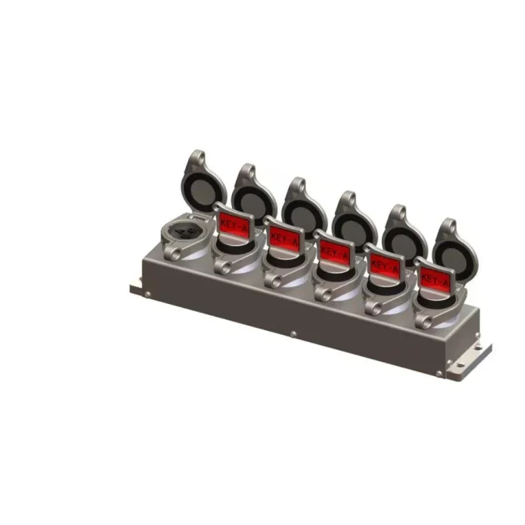
Understanding the Relationship Between Mechanical Interlocks and Industrial Valves
Before looking at individual valve types, it is useful to understand the basic relationship between a valve and an interlock.
A mechanical interlock is designed to restrict or permit a specific mechanical action. Depending on the application, it may control:
-
Valve opening
-
Valve closing
-
Valve position
-
Handle or lever movement
-
Access to an operating mechanism
-
Key removal
-
Sequence between multiple valves
In a typical trapped-key arrangement, the valve position determines whether a key can be removed. That key may then be transferred to another interlock, allowing the next operation to take place.
For example, an operator may be required to close an isolation valve before opening a secondary valve. The first valve's interlock prevents the key from being released until the required position is reached. Once the key is released, it can be transferred to the second interlock.
This creates a physical sequence rather than relying solely on operator memory or written instructions.
The basic principle remains the same across different valves, but the mechanical connection between the interlock and the valve must be adapted to the valve's design.
Mechanical Interlocks for Ball Valves
Ball valves use a rotating ball to control the flow path. A quarter-turn movement of the handle typically changes the valve between open and closed positions.
Their relatively simple operating mechanism makes ball valves suitable for a wide range of industrial applications.
How the Interlock Works
A mechanical interlock for a ball valve generally controls the movement or position of the valve handle.
The interlocking device can be configured so that:
-
The valve is locked in a defined position.
-
The handle cannot be moved without the correct key.
-
A key is released only when the valve reaches the required position.
-
The released key can authorize another operation.
This makes mechanical valve interlocks particularly useful when the position of a ball valve needs to be linked to another process step.
Typical Applications
Ball valve interlocks can be used in:
-
Process isolation
-
Gas systems
-
Chemical processing
-
Utility systems
-
Pipeline applications
-
Equipment maintenance
For example, a ball valve controlling a hazardous gas line may need to remain closed before an access point can be unlocked. A trapped-key configuration can create this physical dependency.
Engineering Considerations
When specifying a ball valve interlock, engineers should consider:
-
Valve size
-
Handle configuration
-
Valve operating direction
-
Available mounting space
-
Required locking position
-
Environmental exposure
The interlock must be securely attached and should not interfere with normal valve operation.
Mechanical Interlocks for Gate Valves
Gate valves are widely used for isolation in pipelines and process systems. Unlike quarter-turn ball valves, gate valves typically require multiple turns of a handwheel to move between fully open and fully closed positions.
This difference in operating mechanism affects interlock design.
How the Interlock Works
A gate valve interlock may be designed to control the handwheel or associated operating mechanism.
The objective may be to ensure that:
-
The valve remains in a required position.
-
The valve cannot be operated without authorization.
-
A key becomes available only after the required position is reached.
Because gate valves have a longer operating movement than quarter-turn valves, the interlock configuration needs to accommodate the valve's operating characteristics.
Why Position Control Matters
Gate valves are often used as isolation devices. In some process systems, the difference between an open and closed valve has major operational consequences.
A properly designed valve interlock system can help prevent accidental operation during maintenance or process switching.
When several gate valves are interconnected, multi-key configurations can also be used to establish a predetermined operating sequence.
Mechanical Interlocks for Butterfly Valves
Butterfly valves use a rotating disc and are commonly operated through a lever, gearbox, or actuator.
Their compact construction makes them popular in:
-
Water treatment
-
HVAC systems
-
Chemical processing
-
Power plants
-
Industrial utilities
-
General process systems
Interlocking the Valve Position
For manually operated butterfly valves, the interlock typically controls the operating lever or gearbox mechanism.
The system may be configured to prevent movement until an authorized key is available.
For example, a butterfly valve may need to remain closed while another line is opened. The key sequence can prevent the second action from occurring until the required valve position has been established.
Special Considerations for Gear-Operated Valves
Larger butterfly valves often use gearboxes because greater operating torque is required.
In these applications, engineers need to consider:
-
Gearbox configuration
-
Valve position indication
-
Mounting arrangement
-
Available space
-
Operating torque
-
Access to the mechanism
A suitable industrial mechanical interlock should be engineered around the actual valve and gearbox rather than selected solely based on valve diameter.
Mechanical Interlocks for Globe Valves
Globe valves are commonly used when flow regulation and throttling are required. Their operating mechanism differs from quarter-turn valves because the valve plug moves linearly through rotation of the handwheel.
Interlock Application
A mechanical interlock may be used to control access to the handwheel or restrict movement under specific operating conditions.
The exact configuration depends on:
-
Valve design
-
Handwheel size
-
Required operating position
-
Process function
-
Interlocking sequence
Globe valves may be integrated into complex process systems where several flow-control points need to be operated in a predetermined order.
In these situations, process safety interlock systems can coordinate the operation of multiple valves.
Mechanical Interlocks for Plug Valves
Plug valves use a cylindrical or tapered plug that rotates to control flow. Like ball and butterfly valves, many plug valves use quarter-turn operation, although designs vary.
Key Interlocking Considerations
A plug valve interlock may control the operating mechanism to ensure that the valve remains in a specified position.
When selecting an interlock, engineers should examine:
-
Plug valve design
-
Handle or gearbox arrangement
-
Operating angle
-
Required locked position
-
Environmental conditions
In chemical and petrochemical applications, material compatibility can also become an important consideration because the interlock may be exposed to corrosive chemicals or vapors.
Mechanical Interlocks for Check Valves
Check valves are different from manually operated valves because they generally operate automatically according to flow direction and pressure conditions.
For this reason, conventional valve interlocking approaches used with manually operated valves may not apply directly.
In applications involving check valves, the interlocking strategy may instead focus on associated isolation valves or access points.
For example, a process system may use:
-
An isolation valve
-
A check valve
-
A drain valve
-
An access point
The mechanical interlock can be designed around the manually operated components to establish a safe isolation sequence.
This illustrates an important principle: mechanical interlocks for industrial applications should be designed around the entire operating procedure rather than a single component in isolation.
Mechanical Interlocks for Needle Valves
Needle valves are commonly used for precise flow control, instrumentation, sampling, and pressure management.
Because they are generally smaller than major process isolation valves, their interlocking requirements may differ.
In critical applications, however, incorrect operation of a small valve can still have significant consequences.
For example, a needle valve may be associated with:
-
Pressure instruments
-
Sampling systems
-
Gas systems
-
Hydraulic circuits
-
Control systems
When such components are part of a critical operating sequence, the interlocking arrangement should account for their role within the wider process.
How Mechanical Interlocks Coordinate Multiple Valve Types
Industrial systems rarely contain only one type of valve.
A single process line may include:
-
Ball valves
-
Gate valves
-
Butterfly valves
-
Globe valves
-
Check valves
-
Drain valves
The challenge is therefore not simply finding an interlock for each valve. Engineers may need to coordinate these different valve types within one safety sequence.
Example of a Mixed-Valve Sequence
Consider a process system containing three valves:
-
A gate valve isolates the main process line.
-
A ball valve controls a secondary supply.
-
A drain valve is used to release residual pressure.
Before maintenance begins, the operating procedure may require:
-
Close the gate valve.
-
Close the ball valve.
-
Open the drain valve.
-
Confirm pressure release.
-
Permit access to the equipment.
A trapped key mechanical interlock can be designed so that each step depends on the completion of the previous one.
The key released from the first operation becomes the authorization for the next step.
This is where mechanical interlocking becomes particularly valuable in complex industrial processes.
Single-Key and Multi-Key Configurations
The choice between single-key and multi-key systems depends largely on the complexity of the operating sequence.
Single-Key Applications
A single-key configuration may be appropriate when one valve needs to be locked or controlled.
Typical examples include:
-
Individual valve isolation
-
Simple equipment protection
-
Local access control
-
Basic manual valve operation
Multi-Key Applications
Multi-key systems are more appropriate when several operating points need to be coordinated.
They can control:
-
Multiple valves
-
Multiple process lines
-
Access doors
-
Electrical isolation points
-
Maintenance procedures
The key exchange mechanism effectively creates a physical logic system.
For complex projects, trapped key interlock systems can provide a reliable way to establish the required sequence.
Conclusion
Mechanical interlocks can be applied to many different types of industrial valves, but the interlocking method must reflect the valve's operating mechanism, configuration, and role within the process.
Ball valves typically require interlocking around quarter-turn handles, while gate and globe valves require solutions compatible with their handwheel-based operating mechanisms. Butterfly valves may involve either lever or gearbox arrangements, and plug valves require consideration of their specific rotary mechanism. Check valves are different again because they normally operate automatically, meaning the interlocking strategy may focus on associated manually operated equipment.
The most important principle is that a mechanical interlock system should not be selected based solely on valve type. Engineers need to consider the complete process sequence, environmental conditions, operating frequency, installation space, and consequences of incorrect operation.
For simple applications, a single interlock may be sufficient. More complex systems may require multi-key mechanical interlocks that coordinate several valves and equipment points through a controlled sequence.
By working with an experienced mechanical interlock supplier, industrial operators can develop reliable valve safety solutions that fit their actual equipment and operating procedures. Properly engineered mechanical interlocks provide a practical physical layer of protection that can help prevent incorrect valve operation and support safer industrial processes.
http://www.nudango.com
nudango -
-
AuthorPosts

- You must be logged in to reply to this topic.